


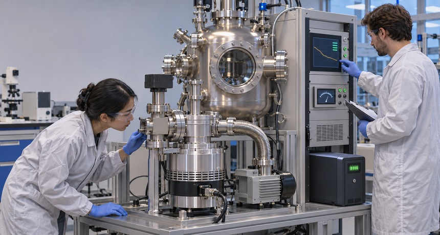
Protecting Turbomolecular Pumps During Power Loss
A power outage does not stop a turbomolecular pump instantly. Its rotor may continue spinning at very high speed while the controller, backing pump, cooling system, gauges, and actuated valves are losing power around it. That mismatch creates the real risk: foreline pressure can rise, a valve can move to an unintended state, oil vapor can migrate upstream, or the system can restart before anyone confirms that conditions are safe.
A resilient shutdown plan treats the pumping train as one coordinated system. The correct sequence depends on the pump, controller, bearings, vent method, process gas, chamber volume, and backing pump. Manufacturer instructions always take priority, but the following design principles help turn a momentary outage into a controlled run-down instead of a contamination or equipment event.
Understand what continues after the power disappears
The rotor stores considerable kinetic energy. Some modern turbomolecular pumps use that rotating mass as a generator during coast-down, allowing the drive electronics to maintain limited communications or operate an approved vent valve for part of the run-down. That capability is model-specific and diminishes as rotor speed falls. A dark display therefore does not prove that the rotor has stopped.
At the same time, the backing pump may stop immediately. Gas load and leakage can then raise foreline pressure while the turbo is still rotating. Cooling water or fans may also stop, and pneumatically operated valves may move according to their spring-return configuration. An outage plan must account for each of those changing states rather than treating the loss of a single power feed as a simple off command.
Start with the controller’s approved failure behavior
Review the exact pump and turbo controller manuals before choosing vent delays, speed thresholds, or automatic-restart settings. Determine how the controller behaves after a supply interruption, which outputs remain energized from regenerated power, how long state signals remain valid, and whether a maintained start input causes an automatic restart when power returns. Lockout and service procedures should assume the rotor can still be moving after indicators go dark.
For a new system, an integrated turbo package can simplify compatibility among the pump, controller, backing pump, cables, and protection accessories. Integration does not eliminate the need to document failure modes, but it reduces the chance that separate components have conflicting shutdown expectations.
Choose a deliberate venting strategy
Controlled venting can slow the rotor, prevent hydrocarbons from diffusing back from an oil-sealed foreline, and place the pump in a known final state. It can also damage a pump if gas enters too quickly, from the wrong port, or as a directed jet against a fast rotor. Never assume that immediate full-flow venting is safe. Use the vent connection, restrictor, gas, timing, and rotational-speed limits specified for the pump.
A controller-operated vent valve may open after a programmed delay or below a defined speed. A power-failure vent valve may rely on the pump’s regenerated energy or its own fail-safe action. In particle-sensitive systems, slow laminar venting may be necessary to avoid disturbing process residue. Purpose-built protect/soft valves and other vacuum valves should be evaluated by function, conductance, actuation, fail position, and compatibility—not flange size alone.
Protect the foreline from pressure rise and backstreaming
The foreline is often where an outage becomes a turbo-pump problem. When the backing pump stops, its inlet pressure may rise. An oil-sealed rotary vane pump may include an anti-suckback mechanism, but that feature must be verified and maintained; it should not be assumed from pump type alone. If the backing pump lacks reliable vacuum retention, the shutdown design may require a dedicated foreline isolation valve or check function.
Valve timing matters. Closing the foreline too early can trap gas at the turbo exhaust, while leaving it open indefinitely can create a path for oil vapor or contaminants. The safe sequence is tied to allowable foreline pressure and the pump’s run-down instructions. Why Foreline Pressure Matters in Turbomolecular Pump Systems explains why the outlet side can affect rotor heating, compression, and stable operation even when chamber pressure appears acceptable.
Use backup power for control, not wishful thinking
A small uninterruptible power supply can be valuable when it is sized for a defined job. Keeping the controller, critical pressure measurement, valve solenoids, and control logic alive long enough to execute a shutdown is usually more practical than trying to operate every pump through an extended outage. List the actual loads, starting currents, required run time, battery aging allowance, and environmental limits before selecting backup capacity.
Separate essential and nonessential loads so an accessory cannot consume the shutdown reserve. Use controller feedback to confirm rotor speed, valve position, and backing-pump status. Appropriate vacuum gauges should remain powered wherever pressure determines whether a valve may move or a pump may restart. Test the backup system under load; a green status light is not a capacity test.
Build interlocks around proven states
A robust sequence uses feedback instead of assuming that a command succeeded. Chamber isolation should be confirmed before venting if the process requires the chamber to remain under vacuum. The controller should verify that the turbo is below the permitted restart or vent threshold. Foreline pressure should be within the pump’s limit before acceleration. Cooling, purge gas, and backing-pump readiness should be proven where the equipment requires them.
The physical layout must support the logic. Short, clearly identified lines and accessible KF flanges and fittings make service boundaries easier to understand, while valve placement determines which volumes remain trapped or protected. Review Why Vacuum Valve Placement Affects Pump-Down and Isolation when defining chamber isolation, foreline isolation, and vent locations. Then test the sequence by removing power at each operating stage, including roughing, acceleration, normal speed, process operation, and run-down.
Inspect before restarting
When power returns, resist the temptation to resume automatically. Confirm that the rotor has stopped or is in the controller-approved state, the chamber and foreline pressures are understood, cooling is available, and all valves report the intended position. Check the event log for overspeed, overtemperature, high foreline pressure, bearing, or communication faults. Inspect the backing pump for oil migration or loss of vacuum retention where applicable.
Record the pressure response and run-down time after a trip. A meaningful change can indicate a leak, vent-valve problem, contamination, bearing issue, or altered gas load. The diagnostic approach in Reading a Pump-Down Curve to Separate Leaks from Outgassing also applies after recovery: compare repeatable data with a known-good baseline instead of relying only on the final pressure.
A practical power-loss review
- Document how the pump, controller, backing pump, cooling, gauges, and every actuated valve behave when power is removed.
- Verify the manufacturer-approved vent port, valve type, gas, opening delay, speed threshold, and maximum pressure-rise rate.
- Define chamber and foreline isolation separately, including each valve’s fail position and position feedback.
- Size backup power for the exact shutdown loads and required duration, then perform a periodic loaded test.
- Disable automatic restart unless the complete system can prove safe conditions without operator inspection.
- Train technicians to treat an unlit controller as potentially containing a spinning rotor.
- Capture trip logs, pressures, valve states, and run-down time so recovery decisions are evidence-based.
Conclusion
Power-loss protection for a turbomolecular pump is not a single accessory. It is a coordinated design that manages stored rotor energy, foreline pressure, venting, isolation, control power, and restart authority. The most reliable systems use model-specific limits, confirmed valve states, useful pressure feedback, and a tested sequence that remains understandable to operators and maintenance staff.
If you are planning a new pumping station or reviewing how an existing system responds to an outage, contact the High Vac Depot team for help selecting compatible pumps, controllers, gauges, valves, fittings, and protection components for the intended operating sequence.





Leave a Reply
You must be logged in to post a comment.