


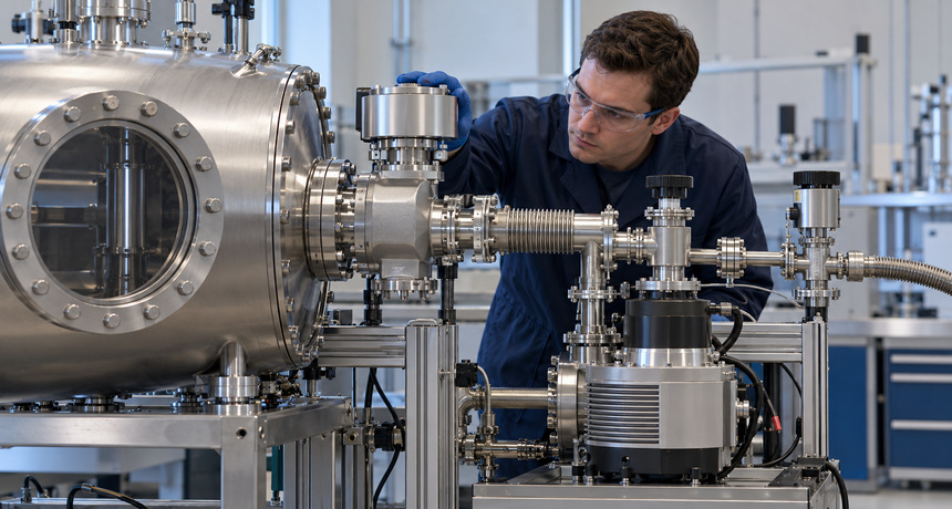
Why Vacuum Valve Placement Affects Pump-Down and Isolation
A vacuum valve is more than an on-off device. Its location determines how much restriction a pump sees, what volume remains trapped after closure, which components stay under vacuum, and whether a pressure-rise test measures the chamber or an assortment of extra plumbing. Two systems built with the same chamber and pump can therefore have very different pump-down times and troubleshooting behavior simply because their valves are arranged differently.
Good placement starts with a clear job for every valve. One may isolate the chamber, another may protect a turbomolecular pump, a third may vent a volume, and a fourth may provide a controlled roughing path. Treating all of them as interchangeable often creates slow cycles, ambiguous pressure readings, and service procedures that depend too heavily on operator memory.
Protect the pumping path from unnecessary restriction
The pump’s rated speed is not automatically the speed delivered to the chamber. Tubing, elbows, fittings, and open valves all have finite conductance. A useful relationship is 1/Sₑff = 1/Sₚᵤₘₚ + 1/C, where Sₑff is effective pumping speed at the chamber and C is the conductance of the connecting path. When conductance is small, installing a larger pump may produce little improvement because the connection remains the controlling resistance.
Keep the main pumping path short, large in diameter, and free of avoidable turns. Select from properly sized vacuum valves rather than assuming that a matching flange size guarantees identical flow performance. A fully open valve should not become the smallest passage in the line. This principle is especially important in molecular flow, where diameter has a strong influence on conductance and a compact restriction can dominate a much longer section of plumbing. The broader relationship among chamber volume, conductance, and pump speed is covered in Properly Sizing a Vacuum System for Your Application.
Place the primary isolation valve close to the chamber
For most high-vacuum systems, the primary isolation valve belongs as close to the chamber port as practical. Closing it then creates a well-defined boundary and leaves only a small connecting volume attached to the chamber. That improves the meaning of a rate-of-rise test, reduces the amount of gas that must be removed after maintenance, and lets the pump or downstream line be serviced while the chamber remains protected.
A large-bore gate valve is often useful where straight-through clearance and high conductance are priorities. The valve still needs room for its actuator and gate mechanism, and its orientation must follow the manufacturer’s instructions. If space or routing requires a turn, angle valves can combine shutoff and a change in direction. Inline valves fit straight runs and may simplify compact assemblies. The choice should reflect flow path, pressure range, seal material, actuation, cycle life, and maintenance access—not only what fits the drawing.
Control the first pressure drop
Opening a large isolation valve between atmosphere and an evacuated line can create a rapid pressure change and high gas velocity. In clean or particle-sensitive equipment, that surge may disturb chamber debris or process material. It can also impose a sudden gas load on downstream equipment. The solution is not to use the main isolation valve as an improvised throttle unless it is designed for that service.
A small bypass or purpose-built protect/soft valve can establish a controlled initial flow before the main valve opens. Once the pressure difference has fallen to an acceptable level, the high-conductance path can open fully. This arrangement makes pump-down more repeatable and reduces pressure shock. The correct crossover pressure and timing must come from the pump, valve, and process requirements; a generic delay timer cannot account for every chamber volume or gas load.
Separate chamber isolation from foreline isolation
A turbomolecular pumping system normally has two distinct boundaries. The high-vacuum isolation valve separates the chamber from the turbo inlet. A foreline valve separates the turbo exhaust from the backing line or backing pump. These valves do different jobs and should be identified separately in piping diagrams, control logic, and maintenance procedures.
The inlet valve protects the chamber and defines the chamber test volume. The foreline valve can limit backstreaming or isolate equipment during service, but closing it at the wrong time can raise outlet pressure while the turbo is still spinning. Follow model-specific operating instructions for turbo pumps and their controllers, and confirm permissible foreline pressure before changing a sequence. Why Foreline Pressure Matters in Turbomolecular Pump Systems explains why conditions downstream of the turbo can affect heat load, compression, and operation even when chamber pressure looks normal.
Place gauges on the side whose pressure matters
A gauge reports local pressure, not a universal system pressure. During high gas flow, the chamber, pump inlet, and foreline can be at meaningfully different pressures. A chamber-control gauge should usually be on the chamber side of the primary isolation valve and positioned away from a direct process-gas jet. A pump-protection gauge belongs where it can measure the condition the controller actually needs to protect.
Use the appropriate vacuum gauges for each pressure range, and label every reading by location. If a rate-of-rise test closes a valve between the gauge and the chamber, the test is measuring the wrong volume. If the gauge remains connected through a long branch, the branch adds surface area and trapped gas to the result. The diagnostic method in Reading a Pump-Down Curve to Separate Leaks from Outgassing becomes much more useful when valve state and gauge location are recorded with the pressure data.
Design isolation for service and leak testing
Valve placement should let a technician isolate a suspect section without venting the entire system. Chamber-side isolation preserves a clean process volume. Pump-side isolation supports blank-off checks and component replacement. A vent connection placed on the intended service volume prevents technicians from loosening hardware to admit air. Keep enough straight length and physical clearance to inspect seals, remove actuators, and use leak-detection probes around joints.
Connection style also defines the maintenance boundary. KF flanges and fittings support quick assembly in many rough- and high-vacuum applications, while CF flanges and fittings support metal-sealed connections for more demanding vacuum and temperature conditions. Place a service valve so the flange that must be opened is on the vented side. Otherwise, a convenient-looking valve may leave the fastener or seal under differential pressure during disassembly.
Build the control sequence around known valve states
Automated systems need more than open and close commands. Position indication can confirm that a valve reached its intended state before the next pump or vent command. Interlocks should consider chamber pressure, foreline pressure, pump speed, backing-pump status, utilities, and the valve’s specified fail position. A normally closed pneumatic valve may provide useful isolation after loss of air or power, but the safest state depends on the equipment and process. There is no universal fail position for every valve in a vacuum system.
Document the sequence in terms that maintenance staff can test: “roughing valve proven closed,” “foreline pressure within limit,” or “high-vacuum valve proven open.” Avoid logic that infers valve position only from the command signal. During commissioning, time the actual transitions and confirm that a fault at each step leaves the system in a recoverable condition.
A practical placement review
- Define each valve’s job: isolation, roughing, venting, pressure control, backflow protection, or service separation.
- Calculate or compare conductance through the complete open path, including the valve body, elbows, reducers, and hoses.
- Put the chamber isolation valve close enough to create a small, unambiguous test volume.
- Provide a controlled initial pumping path when a large pressure difference could disturb particles or overload downstream equipment.
- Locate gauges on the side of each valve that matches the measurement purpose.
- Check access, venting, flange orientation, actuator clearance, and the exact volume exposed during service.
- Verify feedback, interlocks, and failure behavior against every pump and valve manufacturer’s operating instructions.
Conclusion
Thoughtful valve placement preserves effective pumping speed, creates useful isolation boundaries, and makes pressure data easier to interpret. The primary chamber valve should define a compact test volume without restricting flow. Roughing, soft-start, foreline, and vent valves should each have a separate purpose. Gauges and service connections must remain on the side of the boundary they are intended to monitor or protect.
If you are laying out a new vacuum system or revising a line that pumps slowly, tests ambiguously, or is difficult to service, contact the High Vac Depot team for help selecting compatible valves, fittings, gauges, and pumping components for the intended pressure range and operating sequence.







Leave a Reply
You must be logged in to post a comment.